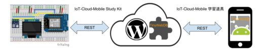
参考:
Smart 自走車是 Webduino 自主研發的產品,專為 Smart 開發板量身打造,輕巧、方便又環保!不僅能 DIY 動手玩創意,還能輕鬆學習程式邏輯概念,實作出一台具個人特色的自走車。
https://tutorials.webduino.io/zh-tw/docs/useful/example/smart-robot-car-assembly.html
Smart 自走車是 Webduino 自主研發的產品,專為 Smart 開發板量身打造,輕巧、方便又環保!這個範例我們會實作如何透過網頁遙控器 ( 電腦、平板、手機皆可 ),就能操控自走車。
https://tutorials.webduino.io/zh-tw/docs/useful/example/smart-robot-car-remote-control.html
Two wheel car use Arduino.
Arduino UNOと同じmini-Oscilloscope を作って見た。
表示の正確性はまた検証が必要だけど
ソースコードはほぼ一緒
/* This is set up to use a 128x64 I2C screen, as available here: http://www.banggood.com/buy/0-96-oled.html For wiring details see http://youtu.be/XHDNXXhg3Hg */ #include <SPI.h> #include <Wire.h> #include <Adafruit_GFX.h> #include <Adafruit_SSD1306.h> #define OLED_RESET 4 Adafruit_SSD1306 display(OLED_RESET); #if (SSD1306_LCDHEIGHT != 64) // error("Height incorrect, please fix Adafruit_SSD1306.h!"); #endif /********************************************/ #define CHARWIDTH 5 #define CHARHEIGHT 8 #define AXISWIDTH (2 + 1) // axis will show two-pixel wide graph ticks, then an empty column #define VISIBLEVALUEPIXELS (128 - AXISWIDTH) // the number of samples visible on screen #define NUMVALUES (2 * VISIBLEVALUEPIXELS) // the total number of samples (take twice as many as visible, to help find trigger point #define TRIGGER_ENABLE_PIN 2 // set this pin high to enable trigger #define SCREEN_UPDATE_ENABLE_PIN 3 // set this pin high to freeze screen byte values[NUMVALUES]; // stores read analog values mapped to 0-63 int pos = 0; // the next position in the value array to read int count = 0; // the total number of times through the loop unsigned long readStartTime = 0; // time when the current sampling started int sampleRate = 1; // A value of 1 will sample every time through the loop, 5 will sample every fifth time etc. const int voutPin = 2; const int VOLT = 3.3; // 3.3Vを電源とした場合 const int ANALOG_MAX = 4096; // ESP32の場合 /********************************************/ // Draws a printf style string at the current cursor position void displayln(const char* format, ...) { char buffer[32]; va_list args; va_start(args, format); vsprintf(buffer, format, args); va_end(args); int len = strlen(buffer); for (uint8_t i = 0; i < len; i++) { display.write(buffer[i]); } } // Draws the graph ticks for the vertical axis void drawAxis() { // graph ticks for (int x = 0; x < 2; x++) { display.drawPixel(x, 0, WHITE); display.drawPixel(x, 13, WHITE); display.drawPixel(x, 26, WHITE); display.drawPixel(x, 38, WHITE); display.drawPixel(x, 50, WHITE); display.drawPixel(x, 63, WHITE); } } // Draws the sampled values void drawValues() { int start = 0; if ( digitalRead(TRIGGER_ENABLE_PIN) ) { // Find the first occurence of zero for (int i = 0; i < NUMVALUES; i++) { if ( values[i] == 0 ) { // Now find the next value that is not zero for (; i < NUMVALUES; i++) { if ( values[i] != 0 ) { start = i; break; } } break; } } // If the trigger point is not within half of our values, we will // not have enough sample points to show the wave correctly if ( start >= VISIBLEVALUEPIXELS ) return; } for (int i = 0; i < VISIBLEVALUEPIXELS; i++) { display.drawPixel(i + AXISWIDTH, 63 - (values[i + start]), WHITE); } } // Shows the time taken to sample the values shown on screen void drawFrameTime(unsigned long us) { display.setCursor(9 * CHARWIDTH, 7 * CHARHEIGHT - 2); // almost at bottom, approximately centered displayln("%ld us", us); } /********************************************/ void setup() { // Set up the display display.begin(SSD1306_SWITCHCAPVCC, 0x3C); // Initialize with the I2C addr 0x3D (for the 128x64) // Clear the buffer. display.clearDisplay(); display.setTextColor(WHITE); pinMode(TRIGGER_ENABLE_PIN, INPUT); pinMode(SCREEN_UPDATE_ENABLE_PIN, INPUT); } /********************************************/ void loop() { // If a sampling run is about to start, record the start time if ( pos == 0 ) readStartTime = micros(); // If this iteration is one we want a sample for, take the sample if ( (++count) % sampleRate == 0 ) values[pos++] = analogRead(voutPin) >> 6; // shifting right by 4 efficiently maps 0-1023 range to 0-63 // If we have filled the sample buffer, display the results on screen if ( pos >= NUMVALUES ) { // Measure how long the run took unsigned long totalSampleTime = (micros() - readStartTime) / 2; // Divide by 2 because we are taking twice as many samples as are shown on the screen // if ( !digitalRead(SCREEN_UPDATE_ENABLE_PIN) ) { // Display the data on screen display.clearDisplay(); drawAxis(); drawValues(); drawFrameTime(totalSampleTime); display.display(); // } // Reset values for the next sampling run pos = 0; count = 0; } }
次の別人アップデート版は気になるけど
TM1637で残り時間の表示。
コードは参考1から利用
#define CLK 2
#define DIO 1
WS2812 LED stripだ
電源の他に、DataはP0につなぐ。
コードは参考1から利用
https://github.com/smartynov/iotfun/tree/master/arduino/deco_lights
WS2812は8個内蔵だから、下記のように変更する
#define PIN 0
#define NUMPIXELS 8
また64個内蔵の場合、BRIGHTNESS を弱めて、下記のように変更する。
#include <Adafruit_NeoPixel.h> // set to pin connected to data input of WS8212 (NeoPixel) strip #define PINGND 0 #define PIN 1 #define PINVCC 2 // any pin with analog input (used to initialize random number generator) #define RNDPIN 2 // number of LEDs (NeoPixels) in your strip // (please note that you need 3 bytes of RAM available for each pixel) #define NUMPIXELS 64 // max LED brightness (1 to 255) – start with low values! // (please note that high brightness requires a LOT of power) #define BRIGHTNESS 32 // increase to get narrow spots, decrease to get wider spots #define FOCUS 65 // decrease to speed up, increase to slow down (it's not a delay actually) #define DELAY 4000 // set to 1 to display FPS rate #define DEBUG 0 Adafruit_NeoPixel strip = Adafruit_NeoPixel(NUMPIXELS, PIN, NEO_GRB + NEO_KHZ800); // we have 3 color spots (reg, green, blue) oscillating along the strip with different speeds float spdr, spdg, spdb; float offset; #if DEBUG // track fps rate long nextms = 0; int pfps = 0, fps = 0; #endif // the real exponent function is too slow, so I created an approximation (only for x < 0) float myexp(float x) { return (1.0/(1.0-(0.634-1.344*x)*x)); } void setup() { pinMode(PINVCC, OUTPUT); digitalWrite(PINVCC, HIGH); pinMode(PINGND, OUTPUT); digitalWrite(PINGND, LOW); // initialize pseudo-random number generator with some random value randomSeed(analogRead(RNDPIN)); // assign random speed to each spot spdr = 1.0 + random(200) / 100.0; spdg = 1.0 + random(200) / 100.0; spdb = 1.0 + random(200) / 100.0; // set random offset so spots start in random locations offset = random(10000) / 100.0; // initialize LED strip strip.begin(); strip.show(); } void loop() { // use real time to recalculate position of each color spot long ms = millis(); // scale time to float value float m = offset + (float)ms/DELAY; // add some non-linearity m = m - 42.5*cos(m/552.0) - 6.5*cos(m/142.0); // recalculate position of each spot (measured on a scale of 0 to 1) float posr = 0.5 + 0.55*sin(m*spdr); float posg = 0.5 + 0.55*sin(m*spdg); float posb = 0.5 + 0.55*sin(m*spdb); // now iterate over each pixel and calculate it's color for (int i=0; i<NUMPIXELS; i++) { // pixel position on a scale from 0.0 to 1.0 float ppos = (float)i / NUMPIXELS; // distance from this pixel to the center of each color spot float dr = ppos-posr; float dg = ppos-posg; float db = ppos-posb; // set each color component from 0 to max BRIGHTNESS, according to Gaussian distribution strip.setPixelColor(i, constrain(BRIGHTNESS*myexp(-FOCUS*dr*dr),0,BRIGHTNESS), constrain(BRIGHTNESS*myexp(-FOCUS*dg*dg),0,BRIGHTNESS), constrain(BRIGHTNESS*myexp(-FOCUS*db*db),0,BRIGHTNESS) ); } #if DEBUG // keep track of FPS rate fps++; if (ms>nextms) { // 1 second passed – reset counter nextms = ms + 1000; pfps = fps; fps = 0; } // show FPS rate by setting one pixel to white strip.setPixelColor(pfps,BRIGHTNESS,BRIGHTNESS,BRIGHTNESS); #endif // send data to LED strip strip.show(); }
アメリカ Digistump LCCの製品。
AVRマイクロコントローラーAtmel Attiny85を搭載しており、小さいながらもArduino IDE(開発環境)を使用し、プログラミングを行うことができる。
Arduinoのソフトウェアをダウンロード(Ver.1.6.6)して、インストールする。
Digisparkのボードパッケージ(Digistump AVR Board)をインストール。
http://digistump.com/package_digistump_index.json
Digistump AVR Boards by Digistumpというのがあるのでそこをクリックしてインストール。
Windows10の場合、ボードパッケージをインストールと次のように警告メッセージが出る。
警告:信頼されていないコントリビューションです。スクリプトの実行をスキップしています(C:\Users\%USERNAME%\Documents\ArduinoData\packages\digistump\tools\micronucleus\2.0a4\post_install.bat)
このパスをコピーし、手動でインストールした。
Digisparkのドライバー(micronucleus-2.0a4-win.zip)をダウンロードして、インストールする必要。
Blink点滅
// the setup routine runs once when you press reset: bool led_stat = false; void setup(){ pinMode(0, true); pinMode(1, true); } void loop(){ digitalWrite(0, led_stat); digitalWrite(1, !led_stat); led_stat = !led_stat; delay(500); }
Fade効果
void setup(){ } void loop(){ for(char i = 0; i < 26; i++){ analogWrite(0, i*10); analogWrite(1, i*10); delay(20); } for(char i = 25; i > 0; i--){ analogWrite(0, i*10); analogWrite(1, i*10); delay(20); } }
マイコンボード:から、Digispark (Default – 16.5mhz) を選択。
書き込み手順:
– 検証でcode自体が通るものであることを確認しておく
– hardwareを抜いた状態で待機
– マイコンボードに書き込むボタンを押す
– 最大60秒のhardware認識待ち状態になる
– hardwareを差す
– 書き込みができる
– 完了!!