WeMos (c4) JSON

WeMosをRESPのクライアントとして機能するため、JSONと、HTTPClientを検証する。

ライブラリの追加

JSONを扱うライブラリに「ArduinoJSON」というのがあるので、ライブラリの追加で、リストが出てくるので、JSONと入力し絞込。

(2018/7現在、5.x と6.x が共存して、6.xはまたベター版のため、エラーが発生する。5.xを利用する)

ArduinoJSONの動作、JsonBuffer size、Parsing program、Serializing programは、下記のURLで確認しながら進める方が便利でしょう。

https://bblanchon.github.io/ArduinoJson/assistant/

動作確認

公式のサンプルJsonParserExampleをそのまんま。

// Copyright Benoit Blanchon 2014-2017
// MIT License
//
// Arduino JSON library
// https://bblanchon.github.io/ArduinoJson/
// If you like this project, please add a star!

#include <ArduinoJson.h>

void setup() {
  Serial.begin(9600);
  while (!Serial) {
    // wait serial port initialization
  }

  // Memory pool for JSON object tree.
  //
  // Inside the brackets, 200 is the size of the pool in bytes,
  // If the JSON object is more complex, you need to increase that value.
  // See https://bblanchon.github.io/ArduinoJson/assistant/
  StaticJsonBuffer<200> jsonBuffer;

  // StaticJsonBuffer allocates memory on the stack, it can be
  // replaced by DynamicJsonBuffer which allocates in the heap.
  //
  // DynamicJsonBuffer  jsonBuffer(200);

  // JSON input string.
  //
  // It's better to use a char[] as shown here.
  // If you use a const char* or a String, ArduinoJson will
  // have to make a copy of the input in the JsonBuffer.
  char json[] =
      "{\"sensor\":\"gps\",\"time\":1351824120,\"data\":[48.756080,2.302038]}";

  // Root of the object tree.
  //
  // It's a reference to the JsonObject, the actual bytes are inside the
  // JsonBuffer with all the other nodes of the object tree.
  // Memory is freed when jsonBuffer goes out of scope.
  JsonObject& root = jsonBuffer.parseObject(json);

  // Test if parsing succeeds.
  if (!root.success()) {
    Serial.println("parseObject() failed");
    return;
  }

  // Fetch values.
  //
  // Most of the time, you can rely on the implicit casts.
  // In other case, you can do root["time"].as<long>();
  const char* sensor = root["sensor"];
  long time = root["time"];
  double latitude = root["data"][0];
  double longitude = root["data"][1];

  // Print values.
  Serial.println(sensor);
  Serial.println(time);
  Serial.println(latitude, 6);
  Serial.println(longitude, 6);
}

void loop() {
  // not used in this example
}

出力

gps
1351824120
48.756080
2.302038

参考

  • https://bblanchon.github.io/ArduinoJson/assistant/ — ArduinoJson Assistant
  • http://shuzo-kino.hateblo.jp/entry/2016/05/06/203603 — ArduinoでJSONを扱う「ArduinoJSON」
  • https://arduinojson.org/v5/assistant/ — How to use ArduinoJson?
    How to compute the JsonBuffer size?
    Paste your JSON in the box and you’ll know…

WeMos (c3) Home IoT Server

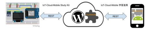
いよいよWiFiManagerを組み込み、理想のIoT-Cloud-Mobile Study Kit (IoT実験キット)の形ができた。

今回の実験はWeMosにhttpサーバを立ち上げて、ブラウザーから接続 を待機;接続するとBMP280センサー情報を返送する。

つまり、スマートフォンまたはPCから直接接続して利用する。この場合ローカル環境の利用に限られ、出かける時でも利用するため、クラウド(例えばTinyWebDB API)が必要だ。

WiFiManagerを組み込みだ、Home IoT Server。

/*
 * 
 */
#include <Wire.h> 
#include <Adafruit_BMP280.h>
#include <Adafruit_GFX.h>
#include <Adafruit_SSD1306.h>
 
#define OLED_RESET 0  // GPIO0
Adafruit_SSD1306 OLED(OLED_RESET);

#define BMP_SCK 13
#define BMP_MISO 12
#define BMP_MOSI 11 
#define BMP_CS 10

Adafruit_BMP280 bmp; // I2C
//Adafruit_BMP280 bmp(BMP_CS); // hardware SPI
//Adafruit_BMP280 bmp(BMP_CS, BMP_MOSI, BMP_MISO,  BMP_SCK);

#include <ESP8266WiFi.h>
#include <DNSServer.h>
#include <ESP8266WebServer.h>
#include <WiFiManager.h> 
 
int ledPin = BUILTIN_LED;
WiFiServer server(80);
 
void setup() {
  OLED.begin();
  OLED.clearDisplay();
 
  //Add stuff into the 'display buffer'
  OLED.setTextWrap(false);
  OLED.setTextSize(1);
  OLED.setTextColor(WHITE);
  OLED.setCursor(0,0);
  delay(10);
 
 
  pinMode(ledPin, OUTPUT);
  digitalWrite(ledPin, HIGH);
 
  // Connect to WiFi network
  OLED.println("wifiManager autoConnect...");
  OLED.display(); //output 'display buffer' to screen  
 
  WiFiManager wifiManager;
  wifiManager.autoConnect();

  OLED.println("WiFi connected");
  OLED.display(); //output 'display buffer' to screen  
 
  // Start the server
  server.begin();
  OLED.println("Server started");
  
  // Print the IP address
  OLED.print("http://");
  OLED.print(WiFi.localIP());
  OLED.println("/");
 
  OLED.display(); //output 'display buffer' to screen  
  // OLED.startscrollleft(0x00, 0x0F); //make display scroll 

  if (!bmp.begin(0x76)) 
  {
    OLED.println("Could not find BMP180 or BMP085 sensor at 0x77");
    OLED.display(); //output 'display buffer' to screen  
    while (1) {}
  }
}

void OLED_show()
{

  OLED.clearDisplay();
  OLED.setCursor(0,0);
  // Print the IP address
  OLED.print("http://");
  OLED.print(WiFi.localIP());
  OLED.println("/");
  OLED.setCursor(0,8);
  OLED.print("Temp = ");
  OLED.print(bmp.readTemperature());
  OLED.println(" Celsius");
  // set the cursor to column 0, line 1
  // (note: line 1 is the second row, since counting begins with 0):
  OLED.setCursor(0,16);
  OLED.print("Pres = ");
  OLED.print(bmp.readPressure());
  OLED.println(" Pascal ");
  // print the number of seconds since reset:
  OLED.setCursor(0,24);
  OLED.print(millis() / 1000);

  OLED.display(); //output 'display buffer' to screen  
}

void loop() {
  delay(500);
  // Check if a client has connected
  WiFiClient client = server.available();
  if (!client) {
    OLED_show();
    delay(1);
    return;
  }
 
  // Wait until the client sends some data
  OLED.println("new client");
  // while(!client.available()){
  //   delay(1);
  // }
 
  // Read the first line of the request
  String request = client.readStringUntil('\r');
  OLED.println(request);
  OLED.display(); //output 'display buffer' to screen  
  client.flush();
 
  // Match the request
 
  int value = LOW;
  if (request.indexOf("/LED=ON") != -1) {
    digitalWrite(ledPin, LOW);
    value = HIGH;
  } 
  if (request.indexOf("/LED=OFF") != -1){
    digitalWrite(ledPin, HIGH);
    value = LOW;
  }


  // Return the response
  client.println("HTTP/1.1 200 OK");
  client.println("Content-Type: text/html");
  client.println(""); //  do not forget this one
  client.println("<!DOCTYPE HTML>");
  client.println("<html>");
 
  client.print("Temp = ");
  client.print(bmp.readTemperature());
  client.println(" Celsius <br>");
  client.print("Pres = ");
  client.print(bmp.readPressure());
  client.println(" Pascal <br>");

  client.print("Led pin is now: ");
 
  if(value == HIGH) {
    client.print("On");  
  } else {
    client.print("Off");
  }
  client.println("<br><br>");
  client.println("Click <a href=\"/LED=ON\">here</a> turn the LED ON<br>");
  client.println("Click <a href=\"/LED=OFF\">here</a> turn the LED OFF<br>");
  client.println("</html>");
 
  delay(1);
  OLED.println("Client disconnected");
  OLED.println("");
  OLED.display(); //output 'display buffer' to screen  
 
}


実験方法:

  1. プログラム検証
  2. WeMosにプログラムアップロード
  3. WeMosのWiFiManeger で接続、AP設定
  4. WeMosのOLEDでIP確認
  5. 自動的にhttpサーバを立ち上げ、ブラウザーから接続 を待機
  6. 接続するとBMP280センサー情報を返送する。


WeMos (8) MAX7219-LED-4x8x8-Matrix

4連装8×8 LEDは数ヶ月前購入したが、発表用タイマーを作りたい。

まず点灯テストから。

googleでなかなかいい事例が見つからないので、githubで検索してみたら、すぐ見つかった。

https://github.com/G6EJD/ESP8266-MAX7219-LED-4x8x8-Matrix-Clock


#include <SPI.h>
#include <Adafruit_GFX.h>
#include <Max72xxPanel.h>
#include <time.h>

int pinCS = D4; // Attach CS to this pin, DIN to MOSI and CLK to SCK (cf http://arduino.cc/en/Reference/SPI )
int numberOfHorizontalDisplays = 4;
int numberOfVerticalDisplays   = 1;
char time_value[20];

// LED Matrix Pin -> ESP8266 Pin
// Vcc            -> 3v  (3V on NodeMCU 3V3 on WEMOS)
// Gnd            -> Gnd (G on NodeMCU)
// DIN            -> D7  (Same Pin for WEMOS)
// CS             -> D4  (Same Pin for WEMOS)
// CLK            -> D5  (Same Pin for WEMOS)

Max72xxPanel matrix = Max72xxPanel(pinCS, numberOfHorizontalDisplays, numberOfVerticalDisplays);

int wait = 70; // In milliseconds

int spacer = 1;
int width  = 5 + spacer; // The font width is 5 pixels

void setup() {
  configTime(0 * 3600, 0, "pool.ntp.org", "time.nist.gov");
  matrix.setIntensity(10); // Use a value between 0 and 15 for brightness
  matrix.setRotation(0, 1);    // The first display is position upside down
  matrix.setRotation(1, 1);    // The first display is position upside down
  matrix.setRotation(2, 1);    // The first display is position upside down
  matrix.setRotation(3, 1);    // The first display is position upside down
}

void loop() {
  matrix.fillScreen(LOW);
  time_t now = time(nullptr);
  String time = String(ctime(&now));
  time.trim();
  time.substring(11,19).toCharArray(time_value, 10); 
  matrix.drawChar(2,0, time_value[0], HIGH,LOW,1); // H
  matrix.drawChar(8,0, time_value[1], HIGH,LOW,1); // HH
  matrix.drawChar(14,0,time_value[2], HIGH,LOW,1); // HH:
  matrix.drawChar(20,0,time_value[3], HIGH,LOW,1); // HH:M
  matrix.drawChar(26,0,time_value[4], HIGH,LOW,1); // HH:MM
  matrix.write(); // Send bitmap to display
  delay(2000);
  display_message(time); // Display time in format 'Wed, Mar 01 16:03:20 2017
}

void display_message(String message){
   for ( int i = 0 ; i < width * message.length() + matrix.width() - spacer; i++ ) {
    //matrix.fillScreen(LOW);
    int letter = i / width;
    int x = (matrix.width() - 1) - i % width;
    int y = (matrix.height() - 8) / 2; // center the text vertically
    while ( x + width - spacer >= 0 && letter >= 0 ) {
      if ( letter < message.length() ) {
        matrix.drawChar(x, y, message[letter], HIGH, LOW, 1); // HIGH LOW means foreground ON, background off, reverse to invert the image
      }
      letter--;
      x -= width;
    }
    matrix.write(); // Send bitmap to display
    delay(wait/2);
  }
}

ほぼそのまま利用だが、Max72xxPanelだけが特殊で、github よりダウンロードして、ライブラリに入れる。

ただその通り繋げ、プログラミングすればできた。

ビデオ映像も参考に

https://photos.app.goo.gl/3Yt4XN4756OtrYEL2

参考:

  • https://github.com/G6EJD/ESP8266-MAX7219-LED-4x8x8-Matrix-Clock
  • https://github.com/markruys/arduino-Max72xxPanel

WeMos (c2) WiFiManager

WeMos のWiFiが、前回のようにSSIDとPASSWORDをコードに書き込む方法の他に、オンライン変更できるような方法もある。

WiFiManager というライブラリを使うと簡単にできる

https://github.com/tzapu/WiFiManager

このソースを参考に試してみる。

まず、ライブラリマネージャーから、WiFiManagerを検索して、インストールする。

ライブラリを使える状態にすると,下記のサンプルで、接続するだけで上のユースケースが満たされて大変便利だ…。標準でWebUIもついてる。

#include <ESP8266WiFi.h>          //https://github.com/esp8266/Arduino

//needed for library
#include <DNSServer.h>
#include <ESP8266WebServer.h>
#include "WiFiManager.h"          //https://github.com/tzapu/WiFiManager

void configModeCallback (WiFiManager *myWiFiManager) {
  Serial.println("Entered config mode");
  Serial.println(WiFi.softAPIP());
  //if you used auto generated SSID, print it
  Serial.println(myWiFiManager->getConfigPortalSSID());
}

void setup() {
  // put your setup code here, to run once:
  Serial.begin(115200);
  
  //WiFiManager
  //Local intialization. Once its business is done, there is no need to keep it around
  WiFiManager wifiManager;
  //reset settings - for testing
  //wifiManager.resetSettings();

  //set callback that gets called when connecting to previous WiFi fails, and enters Access Point mode
  wifiManager.setAPCallback(configModeCallback);

  //fetches ssid and pass and tries to connect
  //if it does not connect it starts an access point with the specified name
  //here  "AutoConnectAP"
  //and goes into a blocking loop awaiting configuration
  if(!wifiManager.autoConnect()) {
    Serial.println("failed to connect and hit timeout");
    //reset and try again, or maybe put it to deep sleep
    ESP.reset();
    delay(1000);
  } 

  //if you get here you have connected to the WiFi
  Serial.println("connected...yeey :)");
 
}

void loop() {
  // put your main code here, to run repeatedly:

}


WiFiManager 動作の流れ

  1. 保存されている認証情報があれば、その情報を使ってAPに接続する
  2. 保存されている情報がないか、あっても接続できなければ、Wi-Fiをスキャンして接続候補となるAPを探し、ESP8266自身がアクセスポイントモードになり、認証情報の入力を待つ
  3. ユーザーがESP8266のAPに接続すると、ESP8266自身が立ち上げたWebサーバーに接続され、表示されているAP候補の中から接続したいAPを選択し、そのパスワードを入力する。
  4. ESP8266は指定されたSSIDとパスワードでAPに接続する

ESP8266アクセスポイントモード

保存されている情報がないか、あっても接続できなければ、Wi-Fiをスキャンして接続候補となるAPを探し、ESP8266自身がアクセスポイントモードになり、認証情報の入力を待つ。

まずスマートフォンの「設定」の中の「Wi-Fi」を開く。自宅のWi-Fiルーターの他に”AutoConnectAP”というAPが見つかります。これがESP8266なので、これを選択。

image

接続したいAPを選択

ユーザーがESP8266のAPに接続すると、ESP8266自身が立ち上げたWebサーバーに接続される。

自動的にブラウザーが立ち上がる場合もありますし、そうでない場合はブラウザーを起動します。するとESP8266のWebサーバーに接続され、次の画面が表示されます。

image

ここで「Configure WiFi」をタップすると、近くにあるWi-Fi APのリストが表示されます。表示されているAP候補の中から接続したいAPを選択し、そのパスワードを入力。するとESP8266は指定されたSSIDとパスワードでAPに接続する。


WeMos (c1) Web on WiFi

いよいよ内蔵WiFiを活用する時期が来た!

前回のセンサー情報をWebからでも見れるようにする。

処理の流れ

setup() {
    WiFi初期化
    Web初期化
    センサー初期化
}
loop() {
    If (Webからリクエスト) 
      .1 パラメタよりLED点/滅
      .2 センサー情報取得
      .3 クライアントに返信
    Else
      .1 センサー情報取得
      .2 LCDに情報表示
}

setup()

  • WiFi 初期化:内蔵WiFiをアクセスポイントに接続
  • Web初期化:内蔵Webサーバを立ち上げる
  • センサー初期化:BMP280を初期化

loop()

  • Webからのリクエストをチェックする

システム構成

完成したプログラム

/*
 * 
 */
#include <Wire.h> 
#include <Adafruit_BMP280.h>
#include <LiquidCrystal_I2C.h>
 
//For SPI connection!
#define BMP_SCK D5
#define BMP_MISO D6
#define BMP_MOSI D7 
#define BMP_CS D3

Adafruit_BMP280 bmp; // I2C
// Adafruit_BMP280 bmp(BMP_CS); // hardware SPI
// Adafruit_BMP280 bmp(BMP_CS, BMP_MOSI, BMP_MISO,  BMP_SCK);

// Set the LCD address to 0x27 for a 16 chars and 2 line display
LiquidCrystal_I2C lcd(0x27, 16, 2);

#include <ESP8266WiFi.h>
 
const char* ssid = "SSID";
const char* password = "WIFI PASS";
 
int ledPin = BUILTIN_LED;
WiFiServer server(80);

void setup()
{
  pinMode(ledPin, OUTPUT);
  digitalWrite(ledPin, HIGH);

  lcd.begin(0,2);  // sda=GPIO_0, scl=GPIO_2

  lcd.init();

  // Turn on the backlight.
  lcd.backlight();
    
  // Connect to WiFi network
  lcd.print("Connect to ");
  lcd.println(ssid);
 
  WiFi.begin(ssid, password);
  lcd.setCursor(0, 1);
 
  while (WiFi.status() != WL_CONNECTED) {
    delay(500);
    lcd.print(".");
  }
  lcd.println("");
  lcd.println("WiFi connected");
 
  // Start the server
  server.begin();
  lcd.println("Server started");
  
  // Print the IP address
  lcd.setCursor(0, 0);
  lcd.print(WiFi.localIP());
  lcd.println("/");

  if (!bmp.begin(0x76)) 
  {
    lcd.println("Could not find BMP180 or BMP085 sensor at 0x77");
    while (1) {}
  }
}

void lcd_show()
{
  lcd.setCursor(0, 1);
  lcd.print(bmp.readTemperature());
  lcd.print("C, ");
  lcd.print(bmp.readPressure() / 100 );
  lcd.print("P ");
  // print the number of seconds since reset:
  lcd.print(millis() / 1000);
  delay(2000);

}

void loop() {
  // Check if a client has connected
  WiFiClient client = server.available();
  if (!client) {
    lcd_show();
    delay(1);
    return;
  }
 
  // Wait until the client sends some data
  lcd.println("new client");
  // while(!client.available()){
  //   delay(1);
  // }
 
  // Read the first line of the request
  String request = client.readStringUntil('\r');
  lcd.println(request);
  client.flush();
 
  // Match the request
 
  int value = LOW;
  if (request.indexOf("/LED=ON") != -1) {
    digitalWrite(ledPin, LOW);
    value = HIGH;
  } 
  if (request.indexOf("/LED=OFF") != -1){
    digitalWrite(ledPin, HIGH);
    value = LOW;
  }


  // Return the response
  client.println("HTTP/1.1 200 OK");
  client.println("Content-Type: text/html");
  client.println(""); //  do not forget this one
  client.println("<!DOCTYPE HTML>");
  client.println("<html>");
 
  client.print("Temp = ");
  client.print(bmp.readTemperature());
  client.println(" Celsius <br>");
  client.print("Pres = ");
  client.print(bmp.readPressure());
  client.println(" Pascal <br>");

  client.print("Led pin is now: ");
 
  if(value == HIGH) {
    client.print("On");  
  } else {
    client.print("Off");
  }
  client.println("<br><br>");
  client.println("Click <a href=\"/LED=ON\">here</a> turn the LED ON<br>");
  client.println("Click <a href=\"/LED=OFF\">here</a> turn the LED OFF<br>");
  client.println("</html>");
 
  delay(1);
  lcd.println("Client disconnected");
 
}


WeMos (b6) I2C (BMP280+1602 LCD)

/*
 * 
 */
#include <Wire.h> 
#include <Adafruit_BMP280.h>
#include <LiquidCrystal_I2C.h>
 
//For SPI connection!
#define BMP_SCK D5
#define BMP_MISO D6
#define BMP_MOSI D7 
#define BMP_CS D3

Adafruit_BMP280 bmp; // I2C
// Adafruit_BMP280 bmp(BMP_CS); // hardware SPI
// Adafruit_BMP280 bmp(BMP_CS, BMP_MOSI, BMP_MISO,  BMP_SCK);

// Set the LCD address to 0x27 for a 16 chars and 2 line display
LiquidCrystal_I2C lcd(0x27, 16, 2);

void setup()
{
  lcd.begin(0,2);  // sda=GPIO_0, scl=GPIO_2

  lcd.init();

  // Turn on the backlight.
  lcd.backlight();
    
  // Print a message to the LCD.
  lcd.print("hello, world!");

  if (!bmp.begin(0x76)) 
  {
    Serial.println("Could not find BMP180 or BMP085 sensor at 0x77");
    while (1) {}
  }
}

void loop()
{
  lcd.setCursor(0, 0);
  lcd.print("Temp = ");
  lcd.print(bmp.readTemperature());
  lcd.println(" Celsius");
     
  // set the cursor to column 0, line 1
  // (note: line 1 is the second row, since counting begins with 0):
  lcd.setCursor(0, 1);
  lcd.print("Pres = ");
  lcd.print(bmp.readPressure());
  lcd.print(" Pascal ");
  // print the number of seconds since reset:
  lcd.print(millis() / 1000);
  delay(2000);

}